
IMS 4.0 Client Software User Manual
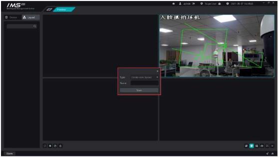
IMS 4.0 Client Software User Manual, This manual is suitable for network surveillance" class="text-sky-600 dark:text-sky-400 font-medium hover:underline" title="Guides for video surveillance">video surveillance software IMS 4.0. This manual describes the use of network video surveillance software to guide you to completethe configuration and operation of network video surveillance software.
Chapter 1Install and start software
(1)double-click “.exe” Install the file and press the wizard to complete the installation.
(2)after the installation is complete, double-click the software program icon to enter the login interface.
(3)for the first time, you need to create a super user and enter a confidentiality issue.
(4)after successfully logging in, the main page is displayed.
Super administrators have and can only create one. The main panel is shown in figure 1-1IMS 4.0 Client Software User Manual
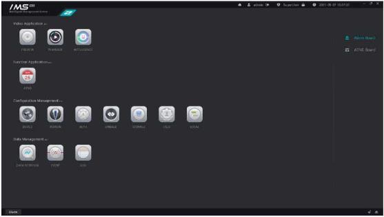 Figure 1-1
After the client software runs, it can manage different types of devices, such as adding, editing, deleting devices, etc., and can also operate device configuration, view device status and so on.
A Note:
To avoid management confusion, it is recommended that a device be managed by only one set of client software.
Please use“Admin”Add devices to user identity.
Equipment management is shown in figure 2-1.
Figure 1-1
After the client software runs, it can manage different types of devices, such as adding, editing, deleting devices, etc., and can also operate device configuration, view device status and so on.
A Note:
To avoid management confusion, it is recommended that a device be managed by only one set of client software.
Please use“Admin”Add devices to user identity.
Equipment management is shown in figure 2-1.
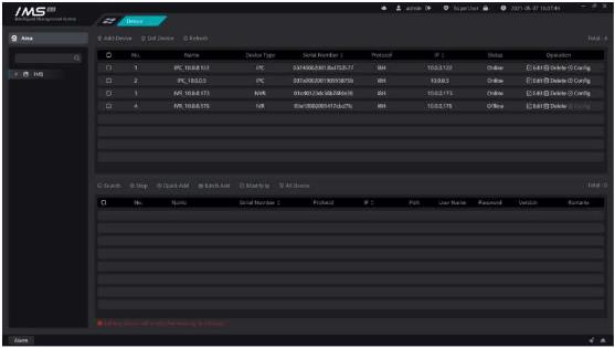 Figure 2-1
The list information shown is: serial number, device name, device type, serial number, protocol, IP, online status.
The area information is added to the IMS 4.0 management system, and the area information presents a multi-level tree structure. A default zone is automatically created when the software is first installed.
Operation steps:
Add areas:
Figure 2-1
The list information shown is: serial number, device name, device type, serial number, protocol, IP, online status.
The area information is added to the IMS 4.0 management system, and the area information presents a multi-level tree structure. A default zone is automatically created when the software is first installed.
Operation steps:
Add areas:
1the mouse covers the area node.
2click [+]Open the add area page, as shown in figure 2-2.
3enter the name of the area.
4click [OK].
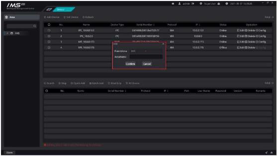 Figure 2-2
£ Note:
The new zone name cannot be more than 30 characters long.
Zone names cannot be duplicated at the same level.
Modify the area name.
X Operation steps:
Figure 2-2
£ Note:
The new zone name cannot be more than 30 characters long.
Zone names cannot be duplicated at the same level.
Modify the area name.
X Operation steps:
1enter the device management page.
2click the button [0] on the area node to open the edit window, as shown in figure 2-3.
3enter a new zone name.
4click [OK] to save.
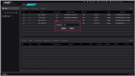 Figure 2-3
The modified area name cannot be more than 30 characters long.
The new zone name cannot be duplicated with other zone names at the same level.
Remove the device from the IMS 4.0 management system.
X Operation steps:
Figure 2-3
The modified area name cannot be more than 30 characters long.
The new zone name cannot be duplicated with other zone names at the same level.
Remove the device from the IMS 4.0 management system.
X Operation steps:
1enter the device management page.
2the mouse overrides the area node to delete.
3click [X] to delete the area.
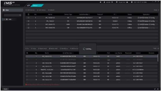 Figure 2-4
[search]: start searching for devices.
[stop]: stop searching for devices.
[quick add]: enter the user name and password of the login device and click OK to add the selected device to the device list through the username password entered.
Figure 2-4
[search]: start searching for devices.
[stop]: stop searching for devices.
[quick add]: enter the user name and password of the login device and click OK to add the selected device to the device list through the username password entered.
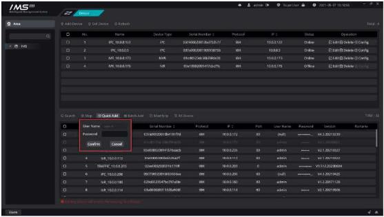 Figure 2-5
.
[batch add]: adds the selected device using the searched user name and password.
[all devices]: all online devices are displayed in the list of online devices.
[no device added]: only online devices that have not been added to the IMS 4.0 management system are displayed in the list of online devices.
A Note:
You must add a zone before you can add the searched device to the IMS 4.0 management system.
After the search is complete, you can click the device name or password of a row to modify the device name and password.
The device name can only be entered up to 40 characters.
The device name cannot contain spaces.
The searched device font color is dark to indicate that the device has been added.
After adding the device, if it appearsthe icon
Qindicates that the device was added
successfully,The icon
O indicates that the device failed to add.
Modify the device IP, subnet mask, gateway.
X Operation steps:
Figure 2-5
.
[batch add]: adds the selected device using the searched user name and password.
[all devices]: all online devices are displayed in the list of online devices.
[no device added]: only online devices that have not been added to the IMS 4.0 management system are displayed in the list of online devices.
A Note:
You must add a zone before you can add the searched device to the IMS 4.0 management system.
After the search is complete, you can click the device name or password of a row to modify the device name and password.
The device name can only be entered up to 40 characters.
The device name cannot contain spaces.
The searched device font color is dark to indicate that the device has been added.
After adding the device, if it appearsthe icon
Qindicates that the device was added
successfully,The icon
O indicates that the device failed to add.
Modify the device IP, subnet mask, gateway.
X Operation steps:
1search equipment.
2double-click the IP of the search list device.
3enter IP, subnet mask, gateway.
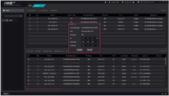 Figure 2-6
.
Modify the device IP, subnet mask, gateway.
X Operation steps:
Figure 2-6
.
Modify the device IP, subnet mask, gateway.
X Operation steps:
1search equipment.
2check the search list device.
3batch modification of IP.
4enter IP, subnet mask, gateway.
5click [OK].
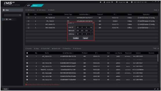 Figure 2-7
Add the online device to the IMS 4.0 management system by entering IP, port, user name, and password.
X Operation steps:
Figure 2-7
Add the online device to the IMS 4.0 management system by entering IP, port, user name, and password.
X Operation steps:
1enter the equipment management interface.
2Click add device to open the add device dialog box.
3input device information.
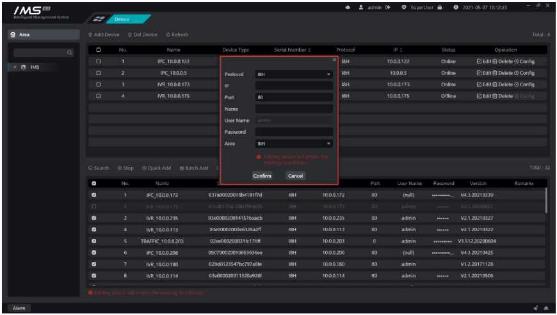 Figure 2-8
£ Note:
You must add a zone before you can search for the device.
The device name can only be entered up to 40 characters.
The device name cannot contain spaces.
When the device is added successfully, the original face database data of the device is
Click on the icon [ 0 ] in the list of devices pop-up window to edit the device information dialog box, you can modify the IP, port, device name, user name, password, area, protocol type, click OK to save.
Figure 2-8
£ Note:
You must add a zone before you can search for the device.
The device name can only be entered up to 40 characters.
The device name cannot contain spaces.
When the device is added successfully, the original face database data of the device is
Click on the icon [ 0 ] in the list of devices pop-up window to edit the device information dialog box, you can modify the IP, port, device name, user name, password, area, protocol type, click OK to save.
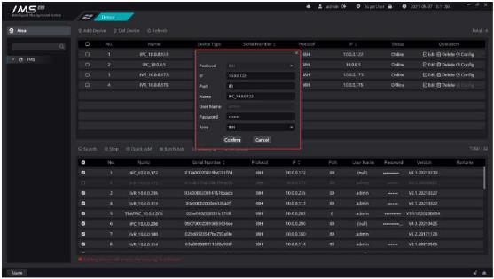 Figure 2-9
.
Remove the device from the IMS 4.0 management system.
X Operation steps:
1 enter the equipment management interface.
2 click the button [0] on the list of devices to confirm deletion.
Figure 2-9
.
Remove the device from the IMS 4.0 management system.
X Operation steps:
1 enter the equipment management interface.
2 click the button [0] on the list of devices to confirm deletion.
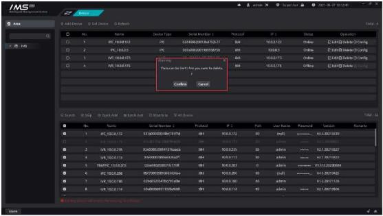 Figure 2-10
.
£ Note:
When you delete a device, you also delete data related to the IMS 4.0 client software on the device, such as sending face pictures through IMS 4.0 client software.
Figure 2-10
.
£ Note:
When you delete a device, you also delete data related to the IMS 4.0 client software on the device, such as sending face pictures through IMS 4.0 client software.
1.10.Log in to cloud devices
1enter the equipment management interface.
2click the button [ ] on the main panel to open the panel for logging in to Yunzhi account
3enter Yunzhi account number and password, and select the area node that the device specifies to add.
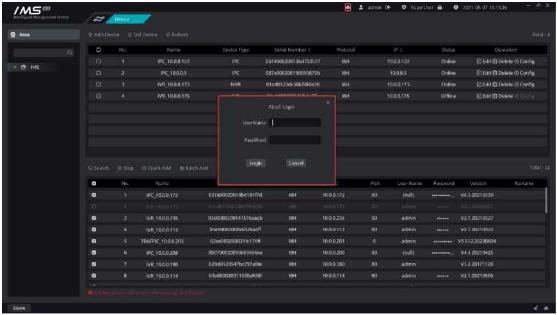 Figure 2-11
.
When you log in successfully, cloud devices are added to the device list:
Figure 2-11
.
When you log in successfully, cloud devices are added to the device list:
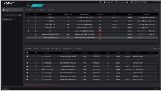 Figure 2-12
Chapter 3 Personnel management
The client management department organizes the tree and the person. Add department, edit department, delete department, add person, editor, delete person, add face and so on. Personnel management is the foundation of the entire IMS 4.0 application.
Figure 2-12
Chapter 3 Personnel management
The client management department organizes the tree and the person. Add department, edit department, delete department, add person, editor, delete person, add face and so on. Personnel management is the foundation of the entire IMS 4.0 application.
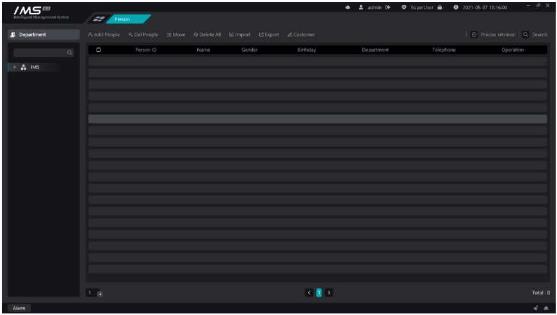 Figure 3-1
.
£ Note:
When there is the icon [o] on the list indicates that the avatar is empty or that the avatar does not meet the criteria and requires a new choice of clear avatar to upload.
Add organization information to IMS 4.0, and the organization information presents a multi-level tree structure. A default department exists after the initial installation.
X Operation steps:
Add departments:
Figure 3-1
.
£ Note:
When there is the icon [o] on the list indicates that the avatar is empty or that the avatar does not meet the criteria and requires a new choice of clear avatar to upload.
Add organization information to IMS 4.0, and the organization information presents a multi-level tree structure. A default department exists after the initial installation.
X Operation steps:
Add departments:
(1)the mouse covers the department node.
(2)Click [+Open the add department page, as shown in figure 3-2.
(3)enter the name of the department.
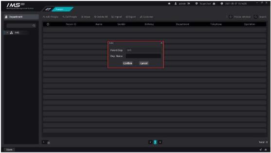 Figure 3-2
.
£ Note:
The name of the subdepartment under the same department cannot be duplicated.
The department name cannot be longer than 24 characters.
The department name cannot be empty.
Change the name of the department.
X Operation steps:
Figure 3-2
.
£ Note:
The name of the subdepartment under the same department cannot be duplicated.
The department name cannot be longer than 24 characters.
The department name cannot be empty.
Change the name of the department.
X Operation steps:
1enter the personnel management page.
2click the button [Ei] on the department node to open the edit window, as shown in figure 3-3.
3enter a new department name.
4click [OK] to save.
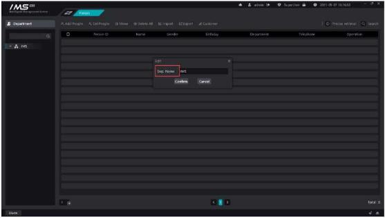 Figure 3-3
.
£ Note:
The name of the subdepartment under the same department cannot be duplicated.
The department name cannot be longer than 24 characters.
The department name cannot be empty.
Remove the department from the IMS 4.0 management system.
X Operation steps:
Figure 3-3
.
£ Note:
The name of the subdepartment under the same department cannot be duplicated.
The department name cannot be longer than 24 characters.
The department name cannot be empty.
Remove the department from the IMS 4.0 management system.
X Operation steps:
1access to the personnel management system.
2the mouse overrides the department node that needs to be deleted.
3click [ X].
4confirm deletion.
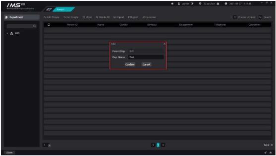 Figure 3-4
.
£ Note:
When deleting a department, you must ensure that the personnel information under this department or all subdepartments under this department has been emptied.
Add personnel information to the IMS 4.0 management system.
X Operation steps:
Figure 3-4
.
£ Note:
When deleting a department, you must ensure that the personnel information under this department or all subdepartments under this department has been emptied.
Add personnel information to the IMS 4.0 management system.
X Operation steps:
1access to the personnel management system.
2click [add person].
3enter the information of personnel information.
4the template of face base database was selected.
5click [save and continue] or click [save].
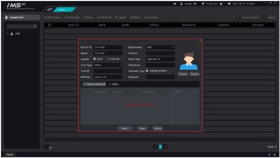 Figure 3-5
.
£ Note:
Personnel number, department, name can not be empty, personnel number can not have spaces.
When the type of document is a resident ID card, the document number is also required.
You cannot set access-control" class="text-sky-600 dark:text-sky-400 font-medium hover:underline" title="Guides for Access Control">access control settings when you do not have a picture set.
The person number must be a unique value.
The entry date and the date of birth must be in the format of XXXX-XX-XX.
You can't set access control settings without setting the avatar.
Adding a face picture can be clipped from a locally selected picture, or a local camera can be turned on to capture it.
X Operation steps:
Click [Select] to open the avatar cutting page, as shown in figure 3-6.
Click [Select] to select the face picture locally, then zoom in and out the cut box, and click [OK].
Click [camera] to turn on the camera on the local computer for capture, and place the capture picture in the clipping box to cut.
Figure 3-5
.
£ Note:
Personnel number, department, name can not be empty, personnel number can not have spaces.
When the type of document is a resident ID card, the document number is also required.
You cannot set access-control" class="text-sky-600 dark:text-sky-400 font-medium hover:underline" title="Guides for Access Control">access control settings when you do not have a picture set.
The person number must be a unique value.
The entry date and the date of birth must be in the format of XXXX-XX-XX.
You can't set access control settings without setting the avatar.
Adding a face picture can be clipped from a locally selected picture, or a local camera can be turned on to capture it.
X Operation steps:
Click [Select] to open the avatar cutting page, as shown in figure 3-6.
Click [Select] to select the face picture locally, then zoom in and out the cut box, and click [OK].
Click [camera] to turn on the camera on the local computer for capture, and place the capture picture in the clipping box to cut.
 Figure 3-6
.
£ Note:
Must choose the front to avoid the crown, five features clear picture, invalid face picture upload server will succeed, but when sent to the device will fail.
The picture must be in JPG format.
Prohibit the use of Meitu tools to process photos to prevent unrecognizable.
Try to use the ID photo as much as possible.
Modify the details of the personnel in the IMS 4.0 management system.
X Operation steps:
Figure 3-6
.
£ Note:
Must choose the front to avoid the crown, five features clear picture, invalid face picture upload server will succeed, but when sent to the device will fail.
The picture must be in JPG format.
Prohibit the use of Meitu tools to process photos to prevent unrecognizable.
Try to use the ID photo as much as possible.
Modify the details of the personnel in the IMS 4.0 management system.
X Operation steps:
1access to the personnel management system.
2click the button [0] at the end of the list of people to enter the editor page
3modify the information of personnel information.
4click [save and continue] or click [save].
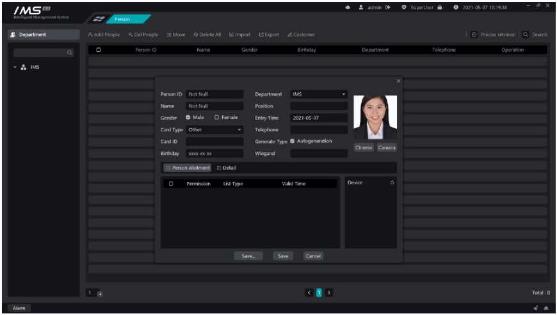 Figure 3-7
.
£ Note:
Personnel number, department, name can not be empty, personnel number can not have spaces.
The person number must be a unique value.
The entry date and the date of birth must be in the format of XXXX-XX-XX.
You can't set access control settings without setting the avatar.
Remove personnel information from the IMS 4.0 management system, and delete personnel operations can be divided into single deletion and bulk deletion.
X Operation steps:
Figure 3-7
.
£ Note:
Personnel number, department, name can not be empty, personnel number can not have spaces.
The person number must be a unique value.
The entry date and the date of birth must be in the format of XXXX-XX-XX.
You can't set access control settings without setting the avatar.
Remove personnel information from the IMS 4.0 management system, and delete personnel operations can be divided into single deletion and bulk deletion.
X Operation steps:
1access to the personnel management system.
2click the button [ĞJ] at the end of the list of people to prompt for a second confirmation, as shown in figure 3-8.
3confirm deletion.
1access to the personnel management system.
2Click the check button [ ] in each line to select the person to be deleted, which means[ ] that it has been selected. Click the check box button [ ] in the header to quickly select the person information on the current page.
3click the button [ Delete person]on the list of people button to prompt for a second confirmation, as shown in figure 3-8.
4confirm deletion.
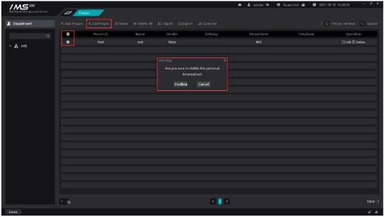 Figure 3-8
.
Figure 3-8
.
3.One-click delete
1access to the personnel management system.
2click the button [
3confirm deletion.
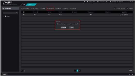 Figure 3-9
.
Note:
Deleting a person also empties all relevant personnel information within a smart device in IMS 4.0.
Move the people selected in the personnel management list to other departments in batches.
X Operation steps:
Figure 3-9
.
Note:
Deleting a person also empties all relevant personnel information within a smart device in IMS 4.0.
Move the people selected in the personnel management list to other departments in batches.
X Operation steps:
1access to the personnel management system.
3click the button [öMove people] on the list of people to open the Select Department dialog box, as shown in figure 3-10.
4select the department to move to.
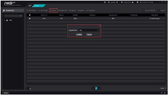 1 bulk import
X Operation steps:
1 access to the personnel management system.
2 click [
EBulk Import] button opens the Select File dialog box.
3 Select the person information ZIP file.
4 Click to open and start the import.
Total: 1
Figure 3-11
.
.
□ Description:
The button for bulk import is disabled during import, and the button resumes the bulk import function.
Note:
Must choose the front to avoid the crown, five features clear picture, invalid face picture upload server will succeed, but when sent to the device will fail.
The picture must be in JPG and PNG format.
Prohibit the use of Meitu tools to process photos to prevent unrecognizable.
Try to use the ID photo as much as possible.
2 batch export
X Operation steps:
1 bulk import
X Operation steps:
1 access to the personnel management system.
2 click [
EBulk Import] button opens the Select File dialog box.
3 Select the person information ZIP file.
4 Click to open and start the import.
Total: 1
Figure 3-11
.
.
□ Description:
The button for bulk import is disabled during import, and the button resumes the bulk import function.
Note:
Must choose the front to avoid the crown, five features clear picture, invalid face picture upload server will succeed, but when sent to the device will fail.
The picture must be in JPG and PNG format.
Prohibit the use of Meitu tools to process photos to prevent unrecognizable.
Try to use the ID photo as much as possible.
2 batch export
X Operation steps:
1access to the personnel management system.
2click [EBatch Export] button opens the Select path dialog box.
3Select the path to store.
4Click on the select folder to begin the export.
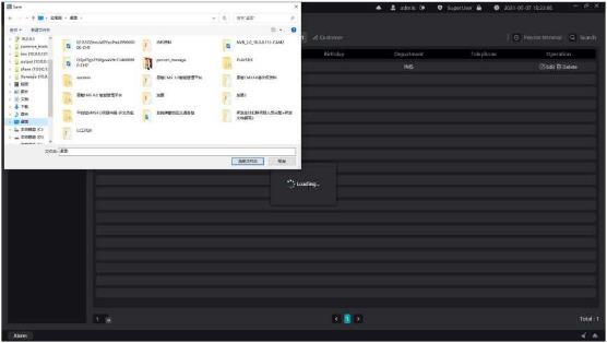 Figure 3-12
.
If you do not have the properties you want to save in the person information, you can add
custom properties.
X Operation steps:
Figure 3-12
.
If you do not have the properties you want to save in the person information, you can add
custom properties.
X Operation steps:
1access to the personnel management system.
2click [ Custom properties] button.
3click [+] to add new properties, the default name is custom properties, modify the property names.
4click [X] to delete properties.
5click [save].
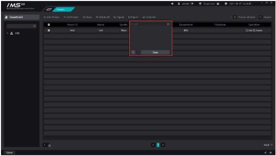 Figure 3-13
.
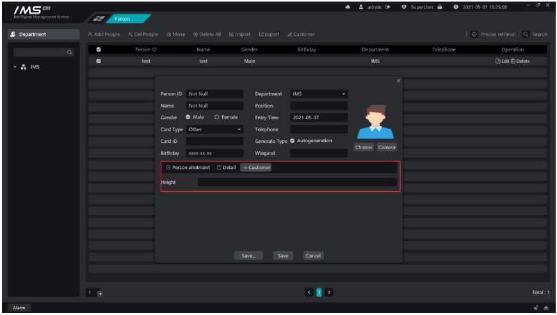
After adding a custom attribute, open the new person page or edit person page again, and the edit panel of the custom attribute will appear.
Figure 3-13
.
After adding a custom attribute, open the new person page or edit person page again, and the edit panel of the custom attribute will appear.
 Chapter 4 Personnel distribution
The device and personnel information are combined, the devices and personnel are grouped, the personnel are assigned to different devices, and the designated person face picture is sent to the designated device, and then the client can receive the face recognition information uploaded by the device.
Establish a grouping to establish a corresponding relationship between the equipment and the personnel, and specify the device to send the face picture.
X Operation steps:
Chapter 4 Personnel distribution
The device and personnel information are combined, the devices and personnel are grouped, the personnel are assigned to different devices, and the designated person face picture is sent to the designated device, and then the client can receive the face recognition information uploaded by the device.
Establish a grouping to establish a corresponding relationship between the equipment and the personnel, and specify the device to send the face picture.
X Operation steps:
1entry into the distribution of personnel.
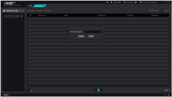 2 click [
].
3 enter the name of the permission group and click OK.
Figure 4-1
£ Note:
Permission group names cannot be repeated.
Permission groups cannot be deleted when there are devices or people in the permission group.
The same person or device can be added to different permission groups.
Add devices to the permission group.
X Operation steps:
2 click [
].
3 enter the name of the permission group and click OK.
Figure 4-1
£ Note:
Permission group names cannot be repeated.
Permission groups cannot be deleted when there are devices or people in the permission group.
The same person or device can be added to different permission groups.
Add devices to the permission group.
X Operation steps:
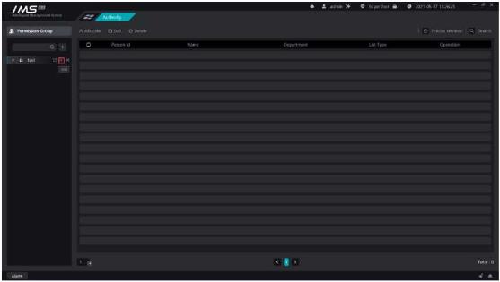
1entry into the distribution of personnel.
2click [ ], as shown in figure 4-2.
3Select the device, as shown in figure 4-3.
 .
.
Figure 4-2
.
.
Figure 4-2
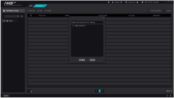 Figure 4-3
The right side of permission group management shows the information about the people added within the permission group: person number, name, department, valid time, list type.
Select a person to add to the permission group.
X Operation steps:
Figure 4-3
The right side of permission group management shows the information about the people added within the permission group: person number, name, department, valid time, list type.
Select a person to add to the permission group.
X Operation steps:
1entry into the distribution of personnel.
2click [p Add people].
3Select people, as shown in figure 4-4.
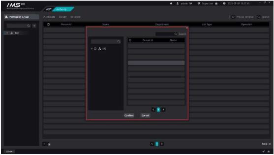 4 click [OK].
Figure 4-4
.
Description
Button
Modify the list type of a person in a permission group
Remove a person from a permission group
Chapter 5 Real-time preview
The main functions of real-time preview are channel preview, viewing device main subcode stream, front-end device intercom, intelligent frame display, capture and so on.
4 click [OK].
Figure 4-4
.
Description
Button
Modify the list type of a person in a permission group
Remove a person from a permission group
Chapter 5 Real-time preview
The main functions of real-time preview are channel preview, viewing device main subcode stream, front-end device intercom, intelligent frame display, capture and so on.
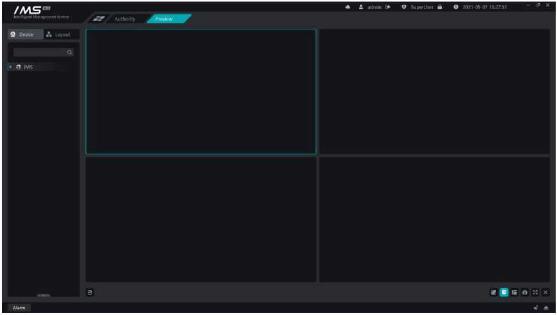 Figure 5-1
.
There are three ways to open real-time video by viewing the real-time video screen of the monitoring point.
1 right-click device on current
X Operation steps:
Figure 5-1
.
There are three ways to open real-time video by viewing the real-time video screen of the monitoring point.
1 right-click device on current
X Operation steps:
1enter the real-time preview interface.
2right-click the device node on the left device tree.
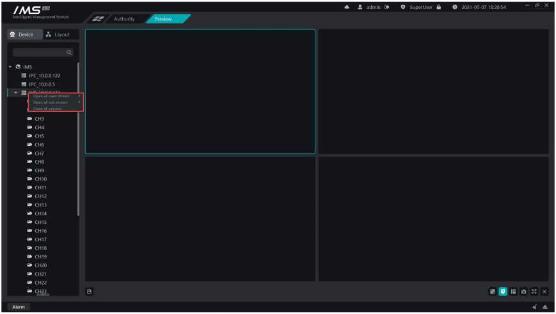
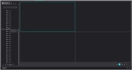
X Operation steps:
1enter the real-time preview interface.
2right-click the channel node on the device tree on the left.
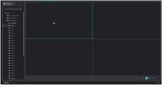 3 select [master stream] or [substream], as shown in figure 5-4
Figure 5-4
.
s Description:
5Region
: equipment
: Channel
CkChannel playback status
Ek: Channel offline state
Description
Button
Intelligent frame
Intercom
Capture
Immediate playback
Monitor
Turn off preview
There are three ways to turn off the real-time preview screen of the current client, and there are three ways to turn off the real-time preview:
3 select [master stream] or [substream], as shown in figure 5-4
Figure 5-4
.
s Description:
5Region
: equipment
: Channel
CkChannel playback status
Ek: Channel offline state
Description
Button
Intelligent frame
Intercom
Capture
Immediate playback
Monitor
Turn off preview
There are three ways to turn off the real-time preview screen of the current client, and there are three ways to turn off the real-time preview:
1close the single window preview.
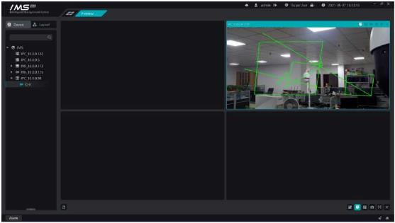 Figure 5-5
.
Figure 5-5
.
2turn off all channel previews under a single device
1.1.right-click the device node that needs to be closed.
1.2.click [close all previews].
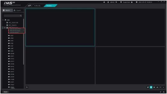 Figure 5-6
.
Figure 5-6
.
1.3.close all previews
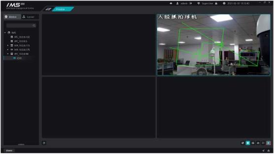 Figure 5-7
.
Set the packet layout so that you can turn on the channel preview in the packet layout.
X Operation steps:
1 set up the split screen.
2 drag and drop the channel to open the flow.
3 click save.
Button
Description
.
Start a round tour.
II
Pause round patrol
.
Stop the wheel patrol
Save the current layout or new layout
Delete layout
ra
Figure 5-7
.
Set the packet layout so that you can turn on the channel preview in the packet layout.
X Operation steps:
1 set up the split screen.
2 drag and drop the channel to open the flow.
3 click save.
Button
Description
.
Start a round tour.
II
Pause round patrol
.
Stop the wheel patrol
Save the current layout or new layout
Delete layout
ra
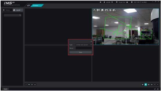 Figure 5-8
IMS 4.0 management system client and front-end device to establish a call connection, and the front-end device for real-time calls to talk to each other.
X Operation steps:
1 When the mouse enters the playback window that needs to be closed, the window title is displayed.
2 click the button [□] to open the intercom.
Figure 5-8
IMS 4.0 management system client and front-end device to establish a call connection, and the front-end device for real-time calls to talk to each other.
X Operation steps:
1 When the mouse enters the playback window that needs to be closed, the window title is displayed.
2 click the button [□] to open the intercom.
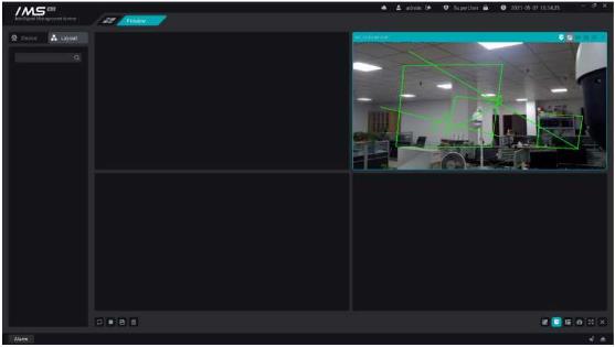 Figure 5-9
.
E Note:
When the intercom function is turned on, it will detect whether the current computer is connected to the microphone, and if the detection fails to turn on the channel intercom, it will also fail.
Intercom is an exclusive resource, and a device can only establish an intercom connection with one client at the same time.
PTZ is to control the rotation, zoom, focal length, aperture, preset point, trajectory, cruising and other functions of the front-end ball machine through the IMS 4.0 management system client, and the rotation speed of the ball machine can be set.
Figure 5-9
.
E Note:
When the intercom function is turned on, it will detect whether the current computer is connected to the microphone, and if the detection fails to turn on the channel intercom, it will also fail.
Intercom is an exclusive resource, and a device can only establish an intercom connection with one client at the same time.
PTZ is to control the rotation, zoom, focal length, aperture, preset point, trajectory, cruising and other functions of the front-end ball machine through the IMS 4.0 management system client, and the rotation speed of the ball machine can be set.
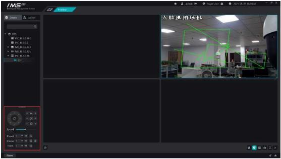 Figure 5-10
s Description:
.
Zoom, click [
] shrink, click [
]zoom in.
S Focal length, click [
] close, click [ + ]distance.
o Aperture, click [
] decrease, click [ + ]increase.
o Set the automatic mode of the cloud station
Set the cloud table to rotate upward
Set the cloud table to rotate down
Set the cloud table to turn to the left
Set the cloud table to turn to the right
Set the cloud table to rotate to the left
Set the cloud table to turn up to the right
Set the cloud table to rotate down to the left
Set the cloud table to turn down to the right
Speed: adjust the rotation speed of the front-end ball machine.
Preset point: click [ -► ]to call the preset point and click [ B ]to set the preset point.
Cruise: click [ -► ]to call the cruise and click [ B ] to set up the cruise and click [ M ]to delete cruises.
Track: click [ ]to call track, click [ B ] to set the trajectory.
Set up cruises
Figure 5-10
s Description:
.
Zoom, click [
] shrink, click [
]zoom in.
S Focal length, click [
] close, click [ + ]distance.
o Aperture, click [
] decrease, click [ + ]increase.
o Set the automatic mode of the cloud station
Set the cloud table to rotate upward
Set the cloud table to rotate down
Set the cloud table to turn to the left
Set the cloud table to turn to the right
Set the cloud table to rotate to the left
Set the cloud table to turn up to the right
Set the cloud table to rotate down to the left
Set the cloud table to turn down to the right
Speed: adjust the rotation speed of the front-end ball machine.
Preset point: click [ -► ]to call the preset point and click [ B ]to set the preset point.
Cruise: click [ -► ]to call the cruise and click [ B ] to set up the cruise and click [ M ]to delete cruises.
Track: click [ ]to call track, click [ B ] to set the trajectory.
Set up cruises
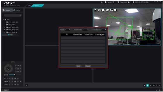 Figure 5-11
£ Note:
The new cruise is added to the end of the cruise list, and the removal cruise is deleted from the last preset point, unable to insert the preset point from the middle or delete the preset point in the middle.
Description
Button
Adjust the size of the playback screen
Intelligent frame display switch
.
i;
Switch split screen
Capture
Full screen
Toggles the playback ratio of the current window playback screen.
X Operation steps:
Figure 5-11
£ Note:
The new cruise is added to the end of the cruise list, and the removal cruise is deleted from the last preset point, unable to insert the preset point from the middle or delete the preset point in the middle.
Description
Button
Adjust the size of the playback screen
Intelligent frame display switch
.
i;
Switch split screen
Capture
Full screen
Toggles the playback ratio of the current window playback screen.
X Operation steps:
1select the playback window that needs to change the playback ratio
2click [ ıs ] to opens the playback screen scale selection box.
3choose the proportion.
1select the playback window where you want to display the smart frame.
2click [5] to displays / hides the smart rule result frame for the current window
1.1.1.show / hide all window rule result frames.
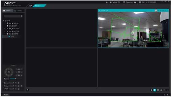 Figure 5-12
.
Set the split screen mode of the real-time preview playback window, which is divided into general mode, wide screen mode and custom mode.
1 there are 14 kinds of screen splitter in conventional mode: 1 screen, 4 screen, 6 sub-screen, 9 sub-screen, 10 sub-screen, 11 sub-screen, 16 sub-screen, 17 sub-screen, 21 sub-screen, 25 sub-screen, 36 sub-screen, 49 sub-screen, 64 sub-screen, 16 sub-screen, 17 sub-screen, 21 sub-screen, 25 sub-screen, 36 sub-screen, 49 sub-screen, 64 split screen.
(2) there are 9 kinds of screen splitter in wide screen mode: 4 split screen, 6 sub screen, 7 sub screen, 9 sub screen, 12 sub screen, 16 sub screen, 24 sub screen, 36 sub screen, 48 sub screen.
Figure 5-12
.
Set the split screen mode of the real-time preview playback window, which is divided into general mode, wide screen mode and custom mode.
1 there are 14 kinds of screen splitter in conventional mode: 1 screen, 4 screen, 6 sub-screen, 9 sub-screen, 10 sub-screen, 11 sub-screen, 16 sub-screen, 17 sub-screen, 21 sub-screen, 25 sub-screen, 36 sub-screen, 49 sub-screen, 64 sub-screen, 16 sub-screen, 17 sub-screen, 21 sub-screen, 25 sub-screen, 36 sub-screen, 49 sub-screen, 64 split screen.
(2) there are 9 kinds of screen splitter in wide screen mode: 4 split screen, 6 sub screen, 7 sub screen, 9 sub screen, 12 sub screen, 16 sub screen, 24 sub screen, 36 sub screen, 48 sub screen.
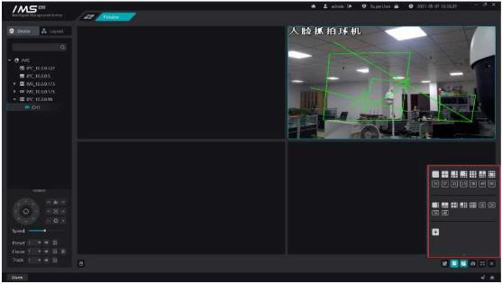 Figure 5-13
.
3 custom mode
X Operation steps:
Figure 5-13
.
3 custom mode
X Operation steps:
1click on the split screen bullet window [ + ] opens a custom split screen window.
2click [add] to add a custom screen name.
3set the width and height of the matrix.
4set the playback window that needs to be merged.
5click [save].
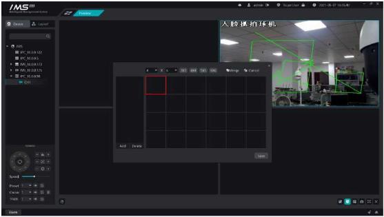 Figure 5-14
.
s Description:
[3X3]: quickly generates a matrix of three rows and three columns.
[4X4]: quickly generates a matrix of four rows and four columns.
[5X5]: quickly generates a matrix of5 rows and 5 columns.
[6X6]: quickly generates a matrix of six rows and six columns.
Drag after the matrix local click to select multiple small windows, click [merge] to merge the selected small windows into one large window, and then click [cancel merge] to restore the large window to multiple small windows.
£ Note:
You can add up to seven custom split screens.
A maximum of 8 ≤ 8 matrices can be set.
Capture the video screen being played by the current focus window to generate a picture and save it locally.
X Operation steps:
1 select the video playback window that needs to be captured
2 click [ a ] capture.
Play window full screen play.
X Operation steps:
Figure 5-14
.
s Description:
[3X3]: quickly generates a matrix of three rows and three columns.
[4X4]: quickly generates a matrix of four rows and four columns.
[5X5]: quickly generates a matrix of5 rows and 5 columns.
[6X6]: quickly generates a matrix of six rows and six columns.
Drag after the matrix local click to select multiple small windows, click [merge] to merge the selected small windows into one large window, and then click [cancel merge] to restore the large window to multiple small windows.
£ Note:
You can add up to seven custom split screens.
A maximum of 8 ≤ 8 matrices can be set.
Capture the video screen being played by the current focus window to generate a picture and save it locally.
X Operation steps:
1 select the video playback window that needs to be captured
2 click [ a ] capture.
Play window full screen play.
X Operation steps:
1click [ - ] full screen.
2right-click to exit the full screen.
1select play window
2click [ ] turn on the audio.
1open the device management page.
2to select a device of type NVR, click the button [ ® ] to enter the device configuration
3choose the function of video planning.
4choose the channel number.
5set video mode, set effective date.
6set the time period for each cycle to take effect on a daily basis.
7set the pre-recording time and video delay.
8ptional: copy the current settings to other dates in the cycle; copy the current settings to other channels.
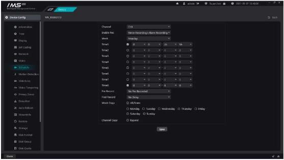 Figure 6-1
Query whether there is a video in the specified channel within the specified time, and draw the queried video clip on the timeline.
X Operation steps:
Figure 6-1
Query whether there is a video in the specified channel within the specified time, and draw the queried video clip on the timeline.
X Operation steps:
1open the video playback page.
2select the location where you want to query the video: device video or storage server video.
3set the query date.
4select the channel to drag and drop to the playback area.
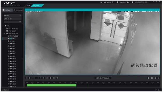 Figure 6-2
.
The left side of the figure represents the name of the query channel, the right side represents the 24-hour timeline a day, the green part represents the regular video of the day of the channel, and the yellow part represents the alarm video of the day of the channel.
£ Note:
Videos of up to nine channels can only be played back at the same time.
IPC needs to insert a memory card to use the video program functionality.
Quartile screen
Nine screen
Video download
Save the video at the front end of the device as a video file in .avi format and store it in a local directory.
Operation steps:
Figure 6-2
.
The left side of the figure represents the name of the query channel, the right side represents the 24-hour timeline a day, the green part represents the regular video of the day of the channel, and the yellow part represents the alarm video of the day of the channel.
£ Note:
Videos of up to nine channels can only be played back at the same time.
IPC needs to insert a memory card to use the video program functionality.
Quartile screen
Nine screen
Video download
Save the video at the front end of the device as a video file in .avi format and store it in a local directory.
Operation steps:
1Select the [type] of the video.
2select the [channel] where the video needs to be downloaded, as shown in figure 6-4.
3set the [start time] and [end time] that need to be downloaded.
4choose the [path] of the video storage.
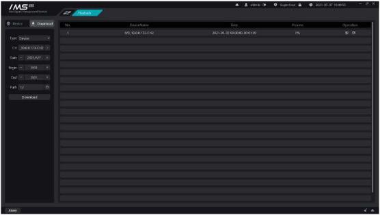 5 click [start].
Figure 6-4
The list on the left shows the currently downloaded tasks and the tasks that have been completed. Displays the channel, time, and progress of the download.
Description
Button
The intelligent application module can view the front-end preview of the intelligent device, receive the capture recognition push, view the capture recognition record, and search for similar face pictures.
5 click [start].
Figure 6-4
The list on the left shows the currently downloaded tasks and the tasks that have been completed. Displays the channel, time, and progress of the download.
Description
Button
The intelligent application module can view the front-end preview of the intelligent device, receive the capture recognition push, view the capture recognition record, and search for similar face pictures.
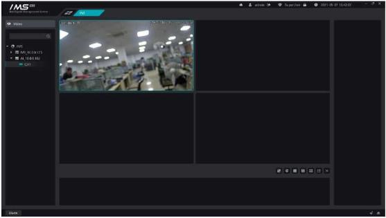 View the front-end real-time preview of the smart monitoring point.
Figure 7-1
There are two ways to open preview in smart application: double-click open, drag and drop release open, specific operation steps can be referred to preview.
Preview the control bar:
Description
Button
Adjust the size of the playback screen
Intelligent frame display switch
Split screen
Query the face capture records, face recognition records stored in the IMS 4.0 client, and capture records that query the internal and source pictures of the device according to the query conditions.
Capture records stored in the IMS 4.0 client.
X Operation steps:
View the front-end real-time preview of the smart monitoring point.
Figure 7-1
There are two ways to open preview in smart application: double-click open, drag and drop release open, specific operation steps can be referred to preview.
Preview the control bar:
Description
Button
Adjust the size of the playback screen
Intelligent frame display switch
Split screen
Query the face capture records, face recognition records stored in the IMS 4.0 client, and capture records that query the internal and source pictures of the device according to the query conditions.
Capture records stored in the IMS 4.0 client.
X Operation steps:
1enter the smart application page.
2click [record].
3click [General].
4select [capture record].
5fill in the filtration conditions: temperature, mask, equipment, date.
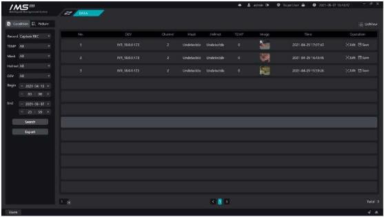 6 click [retrieve].
Figure 8-1
Capture record list operation function:
Description
Button
Add faces to the staff management list
Save the capture image to the local PC
6 click [retrieve].
Figure 8-1
Capture record list operation function:
Description
Button
Add faces to the staff management list
Save the capture image to the local PC
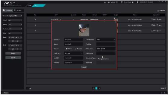 Figure 8-2
.
E Note:
The ID, name and department of the personnel are required.
The birthday format is XXXX-XX-XX.
You can export capture records. After setting the path of the exported file, a CSV file will be generated under the set path to save the capture record information, and the capture device, channel, forehead temperature, time and saved picture path will be recorded in the file, and the corresponding capture picture will be saved under the corresponding picture path.
Query the face recognition records in the IMS 4.0 client.
X Operation steps:
Figure 8-2
.
E Note:
The ID, name and department of the personnel are required.
The birthday format is XXXX-XX-XX.
You can export capture records. After setting the path of the exported file, a CSV file will be generated under the set path to save the capture record information, and the capture device, channel, forehead temperature, time and saved picture path will be recorded in the file, and the corresponding capture picture will be saved under the corresponding picture path.
Query the face recognition records in the IMS 4.0 client.
X Operation steps:
1enter the smart application page.
2click [record].
3click [general].
4Select [identify record].
5fill in the filtering conditions: type, temperature, mask, equipment, name, date.
6click [retrieve].
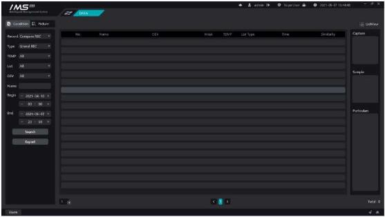 Figure 8-3
.
Similar records are captured on the specified device over a period of time according to the target picture.
X Operation steps:
Figure 8-3
.
Similar records are captured on the specified device over a period of time according to the target picture.
X Operation steps:
1Click on the left dark rectangular area in the figure to select the picture.
2set [start time] and [end time].
3setting [similarity].
4click [search].
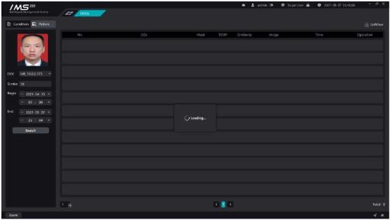 Figure 8-4
Through the attendance management module to configure shift, department scheduling, personnel scheduling. In addition, you can also statistics attendance data, processing check-in, check-out and other attendance.The function of attendance management is to obtain the employee's commuting record according to the identification record received by the intelligent application, and according to the shift information set by the employee to calculate the attendance statistics of the personnel, the following introduces the setting process of attendance configuration.
Figure 8-4
Through the attendance management module to configure shift, department scheduling, personnel scheduling. In addition, you can also statistics attendance data, processing check-in, check-out and other attendance.The function of attendance management is to obtain the employee's commuting record according to the identification record received by the intelligent application, and according to the shift information set by the employee to calculate the attendance statistics of the personnel, the following introduces the setting process of attendance configuration.
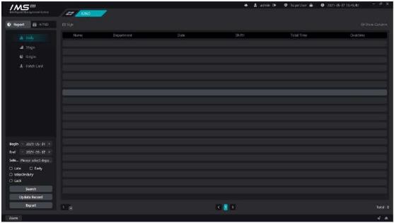 Figure 9-1
Set the time of the week weekend.
Figure 9-1
Set the time of the week weekend.
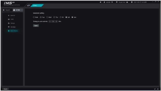 Figure 9-2
.
Select the device that has been added to IMS 4.0 as the attendance point, only if the equipment with the attendance point uploads the face recognition data, can it be used as the attendance check-in data.
X Operation steps:
Figure 9-2
.
Select the device that has been added to IMS 4.0 as the attendance point, only if the equipment with the attendance point uploads the face recognition data, can it be used as the attendance check-in data.
X Operation steps:
1enter the attendance point page.
2click [©Add device].
3selecting equipment.
4click OK.
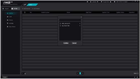 Figure 9-3
£ Note:
The devices that can be selected in the attendance point settings are those added in the equipment management.
The IMS management system goes to the attendance point every ten minutes to get the punch-in records on the device.
Set the daily check-in time range, lunch break, overtime rules, late and early departure rules.
X Operation steps:
Figure 9-3
£ Note:
The devices that can be selected in the attendance point settings are those added in the equipment management.
The IMS management system goes to the attendance point every ten minutes to get the punch-in records on the device.
Set the daily check-in time range, lunch break, overtime rules, late and early departure rules.
X Operation steps:
1set the starting time.
2choose the mode of work.
3set the commuting time.
4set the time range of commuting and signing in.
5choose whether to turn on the lunch break time, and if so, set the lunch break time range. Lunch break does not take into account the length of working hours.
6choose whether to [allow overtime]. If turned on, set the overtime start time and set the minimum overtime unit, as shown in figure 11-9.
7on the premise of allowing overtime, choose whether to [open overtime punch], if open, set the time range of signing in.
8choose whether to turn on [allow the number of hours late], if on, set the time, after opening indicates that after the set working hours exceed the set length of time before signing in late.
9choose whether to turn on [the number of serious late hours], if on, set the time, after opening indicates that after the set working hours exceed the set time, sign in after the serious late.
10choose whether to turn on [the number of hours late for absenteeism], if open, set the time, after opening indicates that after the set working hours exceed the set time, sign in after signing in to take into account absenteeism late.
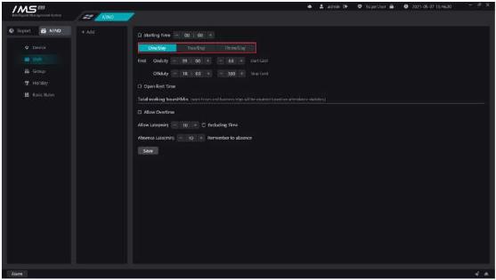 Figure 9-4
.
£ Note:
You can add more than one shift.
The class name is not repeatable.
If you check no punch-in, there is no need to punch in for that period of time, and the system will automatically punch in.
Except that the lunch break must be within the working time range, the rest of the time range settings are not overlapping.
Allow a long time to be late < a long time to be late for work < a long time to be late for work
Set up daily attendance and attendance during the week.
X Operation steps:
Figure 9-4
.
£ Note:
You can add more than one shift.
The class name is not repeatable.
If you check no punch-in, there is no need to punch in for that period of time, and the system will automatically punch in.
Except that the lunch break must be within the working time range, the rest of the time range settings are not overlapping.
Allow a long time to be late < a long time to be late for work < a long time to be late for work
Set up daily attendance and attendance during the week.
X Operation steps:
1click on the attendance group selection button to open the person selection page, as shown in figure 11-13, you can select the entire department as a whole, or select individual participation.
2Select the person or department who needs to participate in the attendance and click [OK].
3choose [attendance group system]. The attendance group system includes: fixed customization, scheduling system, free system.
3.1fixed customization: schedule according to the week, set up the daily shift system from Monday to Sunday, and start over and over again.
(1)set up the shift from Monday to Sunday.
(2)choose [automatic holiday rest]. If the time of work shift within the attendance group coincides with the holidays, rest or work must be arranged according to the holiday settings after automatic rest is enabled.
(3)set [special date].
3.2scheduling: customize the cycle, set the daily shift during the cycle, and then cycle each cycle.
(1)set [cycle days].
(2)set the number of shifts for each day during the cycle.
(3)set up the attendance group [effective time].
(4)set [special date].
3.3Free system: every day of the week, only whether to work or not, free to punch in to and from work, only count the total working hours.
(1)set whether you need to work every day from Monday to Sunday.
(2)set up [signing in node]. The punch-in node indicates that the punch-in before this time node of each day is included in the attendance of the previous day, and the subsequent punch-in is included in the attendance of the day.
4click [save].
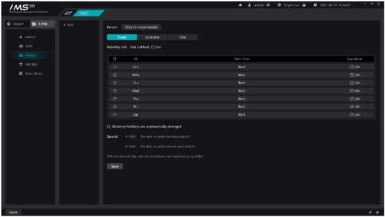 Figure 9-5
.
£ Note:
The participants in the attendance group can be either an organization or an individual, and an organization and an individual can only set up one attendance group. When other attendance groups are set up separately by an organization or individual within the organization, the attendance application takes effect from the attendance group settings set up at the child level.
Priority: the frequency of working day setting is lower than that of legal holiday shift, and the setting of legal holiday shift is lower than that of special date shift.
The new attendance group rules will take effect immediately after they are saved, and the next day after the modification of the attendance group rules will take effect, and the attendance group rules before the amendment will still be used to calculate the attendance on the same day.
Set up legal holidays, when the attendance group management set up legal holidays automatic rest, attendance statistics will be recalculated according to the rest date set in the statutory holidays.
X Operation steps:
Figure 9-5
.
£ Note:
The participants in the attendance group can be either an organization or an individual, and an organization and an individual can only set up one attendance group. When other attendance groups are set up separately by an organization or individual within the organization, the attendance application takes effect from the attendance group settings set up at the child level.
Priority: the frequency of working day setting is lower than that of legal holiday shift, and the setting of legal holiday shift is lower than that of special date shift.
The new attendance group rules will take effect immediately after they are saved, and the next day after the modification of the attendance group rules will take effect, and the attendance group rules before the amendment will still be used to calculate the attendance on the same day.
Set up legal holidays, when the attendance group management set up legal holidays automatic rest, attendance statistics will be recalculated according to the rest date set in the statutory holidays.
X Operation steps:
1.Click on the calendar on the right panel in figure 11-14 and select the date on which you need to rest, indicating that the date has been selected when the date background and font color change.
2.Click [OK].
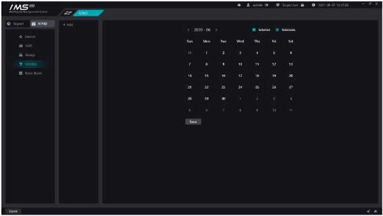 Figure 9-6
.
The report is to generate the daily punch records of individuals according to their respective attendance rules. It can show whether there are a series of abnormal attendance behaviors, such as late, early departure, absenteeism, lack of card and so on, during the attendance period, and can also count the overtime time of the individual in the working day, the overtime time of the rest day, and the overtime time of the holiday. Report functions include: daily statistics, phase summary, original records, supplementary card records.
Count the attendance on a daily basis.
Figure 9-6
.
The report is to generate the daily punch records of individuals according to their respective attendance rules. It can show whether there are a series of abnormal attendance behaviors, such as late, early departure, absenteeism, lack of card and so on, during the attendance period, and can also count the overtime time of the individual in the working day, the overtime time of the rest day, and the overtime time of the holiday. Report functions include: daily statistics, phase summary, original records, supplementary card records.
Count the attendance on a daily basis.
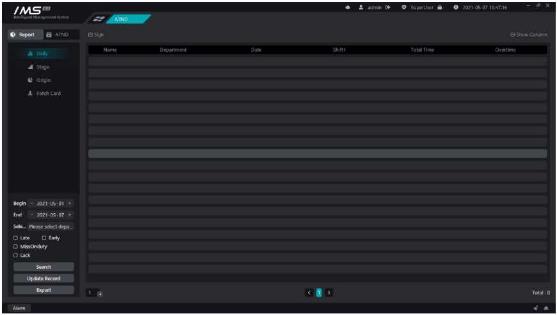 Figure 9-7
.
Daily statistics default display of records: name, department, date, working hours, overtime hours. The name is fixed display, and other contents that can be displayed in the list can be selected by themselves. The options are as follows: department, personnel number, date, attendance 1, attendance 2, attendance 3, punch in time 1, punch in time 2, punch in time 3, work time long, actual work time long, absenteeism times,
late times, serious lateness times, early departure times, late hours, serious late hours, early check-out times, missing cards from work, overtime starting time, overtime punch time, overtime check-in time, It takes a long time to work overtime. Click on figure 11-18 in the upper right corner The icon opens the self-selected display list box, as shown in figure 8-8.
Figure 9-7
.
Daily statistics default display of records: name, department, date, working hours, overtime hours. The name is fixed display, and other contents that can be displayed in the list can be selected by themselves. The options are as follows: department, personnel number, date, attendance 1, attendance 2, attendance 3, punch in time 1, punch in time 2, punch in time 3, work time long, actual work time long, absenteeism times,
late times, serious lateness times, early departure times, late hours, serious late hours, early check-out times, missing cards from work, overtime starting time, overtime punch time, overtime check-in time, It takes a long time to work overtime. Click on figure 11-18 in the upper right corner The icon opens the self-selected display list box, as shown in figure 8-8.
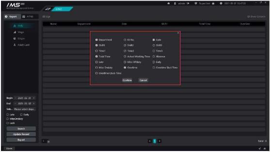 Figure 9-8
.
Attendance during the statistical stage.
Figure 9-8
.
Attendance during the statistical stage.
 Such as 9-9
.
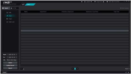
The stage summarizes the records displayed by default: name, department, number of days of attendance, and length of time to work. The name is fixed display, and other contents that can be displayed in the list can be selected by themselves. There are options: departments, personnel numbers, attendance days, working hours, actual working hours, absenteeism times, lateness times, serious lateness times, early departure times, late hours, serious late hours, early departure times, lack of cards at work, number of absenteeism cards, overtime on working days, overtime on rest days, overtime on holidays. Click on the upper right corner of figure 11-20 The icon opens the self-selected display list box, as shown in figure 8-10.
Such as 9-9
.
The stage summarizes the records displayed by default: name, department, number of days of attendance, and length of time to work. The name is fixed display, and other contents that can be displayed in the list can be selected by themselves. There are options: departments, personnel numbers, attendance days, working hours, actual working hours, absenteeism times, lateness times, serious lateness times, early departure times, late hours, serious late hours, early departure times, lack of cards at work, number of absenteeism cards, overtime on working days, overtime on rest days, overtime on holidays. Click on the upper right corner of figure 11-20 The icon opens the self-selected display list box, as shown in figure 8-10.
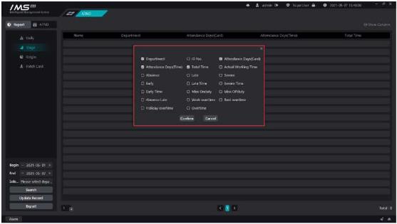 Figure 9-10
By default, the original record shows the name, department, person number, date, time, punch-in equipment, temperature, and summarizes all the personnel attendance records for each attendance point during the retrieval time.
Figure 9-10
By default, the original record shows the name, department, person number, date, time, punch-in equipment, temperature, and summarizes all the personnel attendance records for each attendance point during the retrieval time.
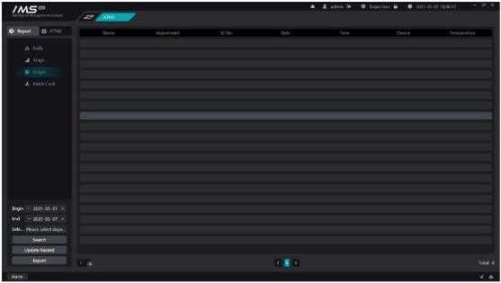 Figure 9-11
.
You can set query conditions before querying the original record: start date, end date, statistician, or department. [export report]: export the attendance summary records and punch records in IMS 4.0 to Excel to save locally. The exported data includes: phase summary, daily statistics, original records, punch time, as shown in figure 8-12.
Figure 9-11
.
You can set query conditions before querying the original record: start date, end date, statistician, or department. [export report]: export the attendance summary records and punch records in IMS 4.0 to Excel to save locally. The exported data includes: phase summary, daily statistics, original records, punch time, as shown in figure 8-12.
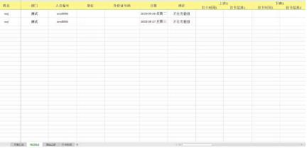 Figure 9-12
.
Displays the information records of all people who make up the card during the retrieval time.
Figure 9-12
.
Displays the information records of all people who make up the card during the retrieval time.
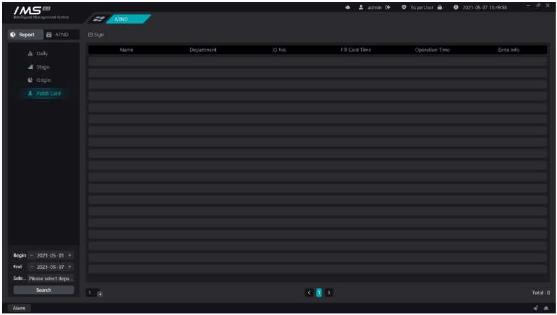 Figure 9-13
.
Displays the employee's card record, showing: name, department, person number, card replacement time, operation time, remarks. When the employee forgets to punch in, the attendance status of the missing card will be generated in the attendance record, click [0Button to open the replacement page for replacement.
X Operation steps:
Figure 9-13
.
Displays the employee's card record, showing: name, department, person number, card replacement time, operation time, remarks. When the employee forgets to punch in, the attendance status of the missing card will be generated in the attendance record, click [0Button to open the replacement page for replacement.
X Operation steps:
1choose [replacement person].
2set the [replacement date].
3set the [replacement time].
4fill in [remarks information].
5click [save].
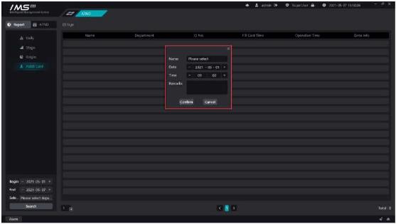 Figure 9-14
.
After the replacement is successfully saved, the daily statistics and phase summary recalculate the report data of the replacement person during the replacement date.
Chapter 10 Storage server
Add the distributed storage server in the local area network, get the disk list of the storage server and set the configuration, set the channel for the storage server and the video mode and recording time of the channel. In the playback module can view video on the storage server side.
X Operation steps:
1 click [
].
Figure 9-14
.
After the replacement is successfully saved, the daily statistics and phase summary recalculate the report data of the replacement person during the replacement date.
Chapter 10 Storage server
Add the distributed storage server in the local area network, get the disk list of the storage server and set the configuration, set the channel for the storage server and the video mode and recording time of the channel. In the playback module can view video on the storage server side.
X Operation steps:
1 click [
].
2enter IP, port, storage device name, user name and password is optional.
3choose whether to empty the configuration within the storage server.
4click [OK].
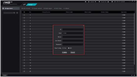 Figure 10-1
.
.
Description
Button
Edit storage server information and currently can only modify the storage server name.
Set storage server quotas.
Remove the storage server from the IMS system.
Click the quota button on the storage server tree to open the quota list for the current storage server. The information shown in the list is the hard disk number of the current storage server, the partition, the free space for each partition, the video space, and the quota size.
X Operation steps:
1 click [0].
Figure 10-1
.
.
Description
Button
Edit storage server information and currently can only modify the storage server name.
Set storage server quotas.
Remove the storage server from the IMS system.
Click the quota button on the storage server tree to open the quota list for the current storage server. The information shown in the list is the hard disk number of the current storage server, the partition, the free space for each partition, the video space, and the quota size.
X Operation steps:
1 click [0].
2enter the quota size.
3click [OK].
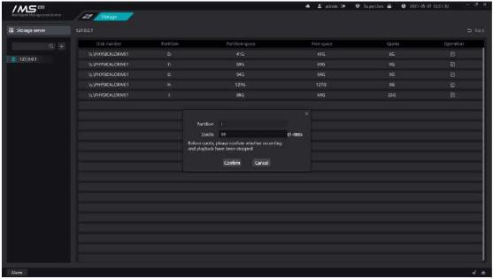 Figure 10-2
.
E Note:
All video or stored video playback needs to be stopped before setting quotas.
Add the channel first.
X Operation steps:
Figure 10-2
.
E Note:
All video or stored video playback needs to be stopped before setting quotas.
Add the channel first.
X Operation steps:
1click [add Channel].
2select the channel.
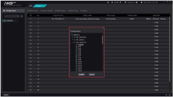 3 click [OK].
Figure-10-3
Description
Button
Configure channel video mode and time.
Delete the channel.
Click on the [ Open the channel video mode configuration page
3 click [OK].
Figure-10-3
Description
Button
Configure channel video mode and time.
Delete the channel.
Click on the [ Open the channel video mode configuration page
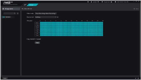 Figure 10-4
X Operation steps:
1 click on the [in the channel list operation] Icon opens the video page.
Figure 10-4
X Operation steps:
1 click on the [in the channel list operation] Icon opens the video page.
3choose
4time plan setting, can quickly apply template.
5if you want to copy the video mode settings for the current channel to another channel, check [expand] and check the other channels to which you want to copy.
6click [save].
2click [ ]to add a template name.
3in the time area, select the time clips that need to be videotaped.
4click [save].
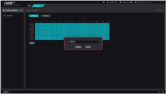 Figure 10-5
Set up IMS 4.0 management system administrators and operators. Administrators or operators log on to the IMS 4.0 management system with only partial functional permissions.
X Operation steps:
Figure 10-5
Set up IMS 4.0 management system administrators and operators. Administrators or operators log on to the IMS 4.0 management system with only partial functional permissions.
X Operation steps:
1add new user.
2set [user type].
3set [user name].
4set [password].
5set [user rights].
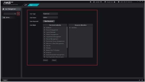 Figure 11-1
When the device generates an alarm push to IMS 4.0, the client responds to the associated action. Linkage rules are a set of rules that associate alarm with action.
The left device expands and clicks the channel node, the right table shows the corresponding event type of the channel, and the event types displayed by different devices are not the same.
The event types of binocular recognition temperature measurement equipment are: blacklist,
mask detection, helmet detection, temperature anomaly.
Figure 11-1
When the device generates an alarm push to IMS 4.0, the client responds to the associated action. Linkage rules are a set of rules that associate alarm with action.
The left device expands and clicks the channel node, the right table shows the corresponding event type of the channel, and the event types displayed by different devices are not the same.
The event types of binocular recognition temperature measurement equipment are: blacklist,
mask detection, helmet detection, temperature anomaly.
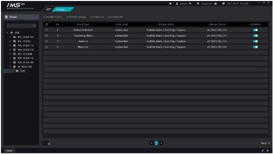 Figure 12-1
.
The event types of intelligent IPC and other devices are: mobile detection, video loss, video occlusion, alarm input, target count, electronic fence, item legacy loss, virtual warning line, retrograde detection, departure detection.
Figure 12-1
.
The event types of intelligent IPC and other devices are: mobile detection, video loss, video occlusion, alarm input, target count, electronic fence, item legacy loss, virtual warning line, retrograde detection, departure detection.
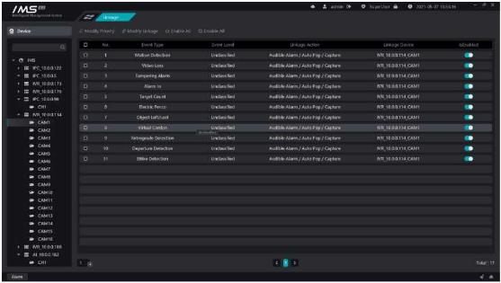 Figure 12-2
.
s Description:
The priority type is divided into general, important and urgent. After adding the device successfully, the default type is unclassified, and the priority execution order is emergency-important-general-unclassified. When multiple alarms are received at the same time, the alarm linkage with high priority is triggered first.
Linkage action refers to when the device generates an alarm and is pushed to the client, the client makes the corresponding action according to the binding rules. The linkage action includes: sound alarm, automatic bounce window, map display.
X Operation steps:
Figure 12-2
.
s Description:
The priority type is divided into general, important and urgent. After adding the device successfully, the default type is unclassified, and the priority execution order is emergency-important-general-unclassified. When multiple alarms are received at the same time, the alarm linkage with high priority is triggered first.
Linkage action refers to when the device generates an alarm and is pushed to the client, the client makes the corresponding action according to the binding rules. The linkage action includes: sound alarm, automatic bounce window, map display.
X Operation steps:
1select the channel.
2select the alarm type.
3click [modify linkage].
4set up linkage action and select linkage channel.
5click save.
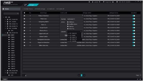 Figure 12-3
Chapter 13 Event center
The event center is mainly to receive the alarm sent by the equipment and generate alarm linkage as well as to view the historical alarm.
The alarm is immediately pushed to the client, and after receiving the alarm, the corresponding response is made according to the linkage action bound in the linkage rule.
Figure 12-3
Chapter 13 Event center
The event center is mainly to receive the alarm sent by the equipment and generate alarm linkage as well as to view the historical alarm.
The alarm is immediately pushed to the client, and after receiving the alarm, the corresponding response is made according to the linkage action bound in the linkage rule.
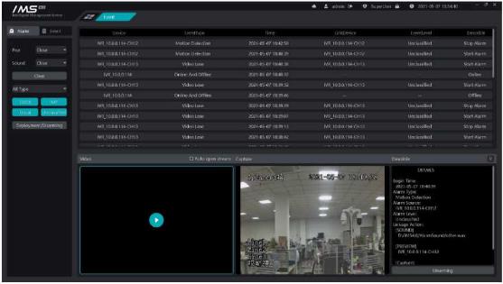 Figure 13-1
The information shown in the list in figure 13-1 is the event alarm that the device pushes to IMS 4.0 in real time. The information displayed is the name of the alarm source device, the alarm type, the alarm time, the linkage device, the event level, and the description. Figure 13-1 the central area is used to display device previews, front-end capture pictures, and event descriptions.
[pop window]: sets whether the pop window is displayed and how long it is displayed. The pop-up window setting option is: close, 5 seconds, 15 seconds, 30 seconds. When set to off, the automatic bounce window is not enabled, and the preview of the linkage is played automatically in the preview area below. When set to [5 seconds], [15 seconds], [30 seconds] means that the preview automatic pop-up window closes the preview time for 5 seconds, 15 seconds, and 30 seconds, respectively.
Figure 13-1
The information shown in the list in figure 13-1 is the event alarm that the device pushes to IMS 4.0 in real time. The information displayed is the name of the alarm source device, the alarm type, the alarm time, the linkage device, the event level, and the description. Figure 13-1 the central area is used to display device previews, front-end capture pictures, and event descriptions.
[pop window]: sets whether the pop window is displayed and how long it is displayed. The pop-up window setting option is: close, 5 seconds, 15 seconds, 30 seconds. When set to off, the automatic bounce window is not enabled, and the preview of the linkage is played automatically in the preview area below. When set to [5 seconds], [15 seconds], [30 seconds] means that the preview automatic pop-up window closes the preview time for 5 seconds, 15 seconds, and 30 seconds, respectively.
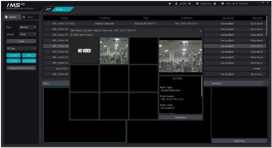 Figure 13-2
.
S Description:
[clear]: clear data from the list
[turn on sound]: turn on alarm linkage alarm sound.
[turn off sound]: turn off alarm linkage alarm sound.
[general]: overcare real-time alarm, only receive events with a general event priority.
[serious]: overworry real-time alarm, only receive events with serious event priority.
[emergency]: overworry real-time alarm, only receive events with an emergency priority.
[not set]: overworry real-time alarm and receive only events whose event priority is not set.
[type]: click on the type list to filter received events, mobile detection, video loss, video occlusion, alarm input, electronic fence, item legacy loss, virtual warning line, retrograde detection, departure detection, temperature anomaly, blacklist, mask detection.
Event query is mainly to query the historical event information in accordance with specific conditions, and to view the video information and picture information related to historical events.
X Operation steps:
Figure 13-2
.
S Description:
[clear]: clear data from the list
[turn on sound]: turn on alarm linkage alarm sound.
[turn off sound]: turn off alarm linkage alarm sound.
[general]: overcare real-time alarm, only receive events with a general event priority.
[serious]: overworry real-time alarm, only receive events with serious event priority.
[emergency]: overworry real-time alarm, only receive events with an emergency priority.
[not set]: overworry real-time alarm and receive only events whose event priority is not set.
[type]: click on the type list to filter received events, mobile detection, video loss, video occlusion, alarm input, electronic fence, item legacy loss, virtual warning line, retrograde detection, departure detection, temperature anomaly, blacklist, mask detection.
Event query is mainly to query the historical event information in accordance with specific conditions, and to view the video information and picture information related to historical events.
X Operation steps:
1select the device channel.
2set event priority.
3set the time range of the event.
4set the event type.
5click [search].
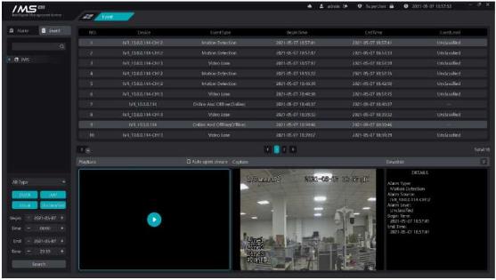 Figure 13-3
.
The left side is the conditional selection area, the upper half is divided into the device tree, the middle is the event priority, and the following is the time range of the event generation. Double-click the retrieval results can play the video information of the alarm source or linkage equipment in the playback area, the video start time is 5 seconds before the start of the alarm, and the end time is 5 seconds after the end of the alarm. If the alarm has a capture, the alarm capture picture is displayed in the capture area.
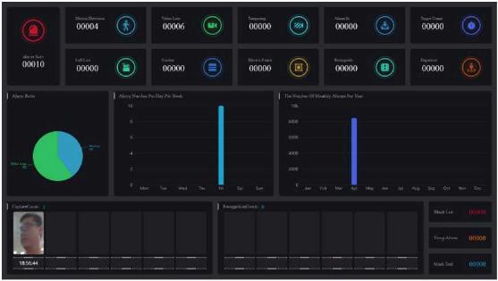
View alarm statistics.
.
Figure 13-4
13.4. Attendance board
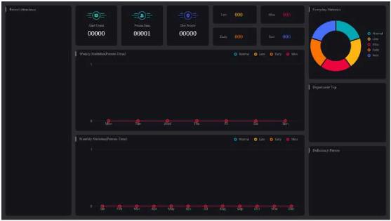
Check attendance statistics.
Figure 13-5
Figure 13-3
.
The left side is the conditional selection area, the upper half is divided into the device tree, the middle is the event priority, and the following is the time range of the event generation. Double-click the retrieval results can play the video information of the alarm source or linkage equipment in the playback area, the video start time is 5 seconds before the start of the alarm, and the end time is 5 seconds after the end of the alarm. If the alarm has a capture, the alarm capture picture is displayed in the capture area.
View alarm statistics.
.
Figure 13-4
13.4. Attendance board
Check attendance statistics.
Figure 13-5
 Chapter 14 Log management
Record the operation log in the IMS 4.0 management system.
X Operation steps:
Chapter 14 Log management
Record the operation log in the IMS 4.0 management system.
X Operation steps:
1select the type, and the type can be selected more.
2enter the user name, the user name is all matched.
3set the start time and end time.
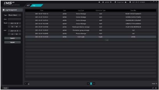 Figure 14-1
Chapter 15 System setup
Read the local configuration of the system to modify.
X Operation steps:
Figure 14-1
Chapter 15 System setup
Read the local configuration of the system to modify.
X Operation steps:
1enter the public configuration.
2modify the configuration information.
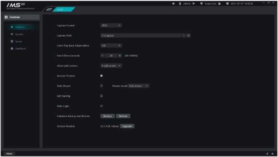 Figure 15-1
.
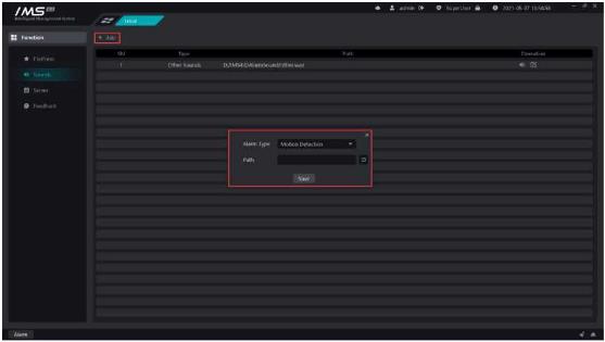
Customize the sound of setting event linkage alarms.
x Operation steps:
Figure 15-1
.
Customize the sound of setting event linkage alarms.
x Operation steps:
1enter the sound configuration.
2click [+Add] button.
3select the type of alarm.
4set the sound file path.
5click [save]
 Audition
b)
Modify the sound file path
Delete a custom alarm sound
£ Note:
If the alarm type does not have a custom sound, the sound file for other sounds is played when the alarm type is linked.
Other sound types cannot be deleted.
When the equipment is disconnected and reconnected.
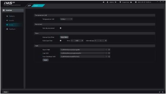
Equipment timing correction
Set the picture path of linkage capture picture, face capture picture, identity authentication
.
picture.
Figure 15-3
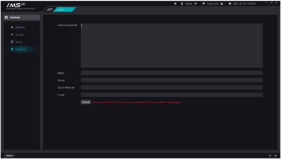
15.4. Feedback
Thank you very much for your valuable advice on our software during your busy schedule.
Figure 15-5
Audition
b)
Modify the sound file path
Delete a custom alarm sound
£ Note:
If the alarm type does not have a custom sound, the sound file for other sounds is played when the alarm type is linked.
Other sound types cannot be deleted.
When the equipment is disconnected and reconnected.
Equipment timing correction
Set the picture path of linkage capture picture, face capture picture, identity authentication
.
picture.
Figure 15-3
15.4. Feedback
Thank you very much for your valuable advice on our software during your busy schedule.
Figure 15-5
Advertisement

Topics:
#Ims 4 0 Camera Connection
#Ims 4 0 Client Configuration
#Ims 4 0 Client Software Tutorial
#Ims 4 0 Client Software User Manual
#Ims 4 0 Client Troubleshooting
#IMS 4.0 CMS integration
#IMS 4.0 installation guide
#IMS 4.0 login setup
#IMS 4.0 network configuration
#IMS 4.0 NVR connection
#IMS 4.0 playback guide
#IMS 4.0 recording setup
#IMS 4.0 remote access
#IMS 4.0 security settings
#IMS 4.0 software download
#IMS 4.0 software error
#IMS 4.0 software setup
#IMS 4.0 system requirements
#IMS 4.0 update firmware
#IMS 4.0 user management
#IMS 4.0 video monitoring software
Did this security guide help you?
Rate this article to help fellow engineers find the best guides.

Written by
Alex Vance
Senior Security Systems Architect & IoT Consultant with over 15 years in digital surveillance design.
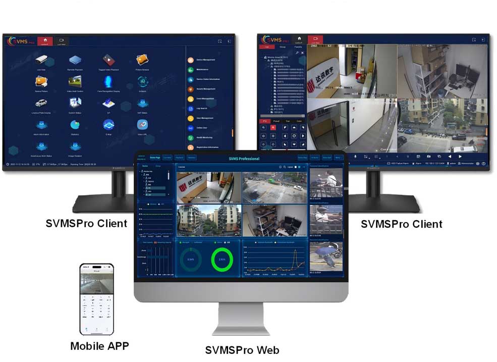
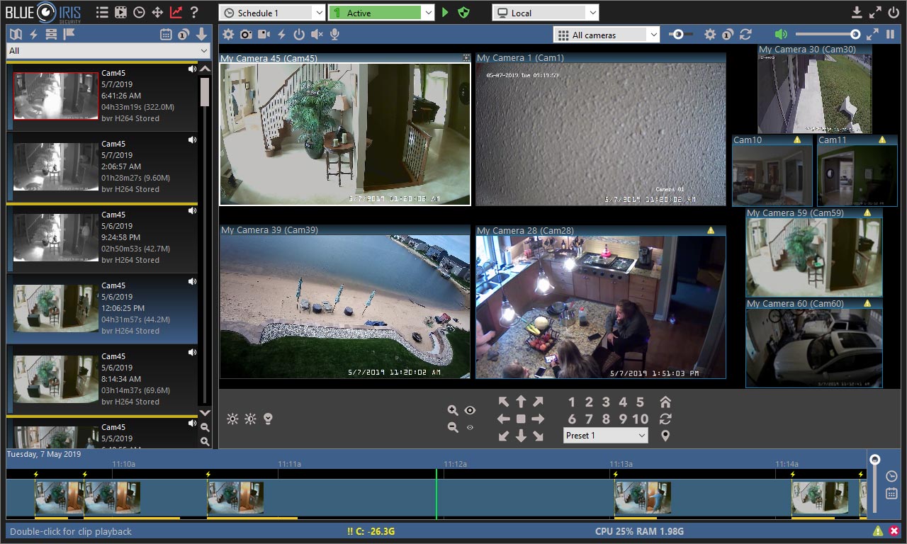
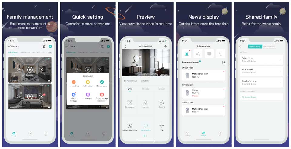
Discussion (0)
No comments yet. Be the first to share your thoughts!
Leave a Comment